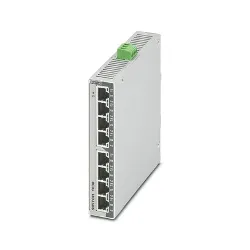
IB IL AI 4/EF-XC-PAC - Analog module
2701215
Inline, Analog input terminal, Analog inputs: 4, 0 V ... 5 V, -5 V ... 5 V, 0 V ... 10 V, -10 V ... 10 V, 0 mA ... 20 mA, 4 mA ... 20 mA, -20 mA ... 20 mA, connection technology: 2-, 3-, 4-conductor, transmission speed in the local bus: 500 kbps, Extreme conditions version, degree of protection: IP20, including Inline connectors and marking fields
The terminal is designed for use within an Inline station. It is used to acquire analog voltage and current signals. Thanks to special engineering measures and tests, the terminal can be used under extreme ambient conditions.
Dimensional drawing
Width 48.8 mm
Height 135 mm
Depth 71.5 mm
Note on dimensions Housing dimensions
Inline local bus
Number of interfaces 2
Connection method Inline data jumper
Transmission speed 500 kbps
Module
ID code (dec.) 223
ID code (hex) DF
Length code (hex) 05
Length code (dec) 05
Process data channel 80 bit
Input address area 10 Byte
Output address area 10 Byte
Register length 96 bit
Required parameter data 28 Byte
Required configuration data 4 Byte
Analog: General
Input name Analog inputs
Description of the input Differential input, including sensor supply (24 V DC)
Number of inputs 4
A/D conversion time max. 10 µs
A/D converter resolution 16 bit
Connection method Inline shield connector
Connection technology 2-, 3-, 4-conductor
Note regarding the connection technology shielded
Current input signal 0 mA ... 20 mA
4 mA ... 20 mA
-20 mA ... 20 mA
Input resistance current input typ. 110 Ω
Voltage input signal 0 V ... 5 V
-5 V ... 5 V
0 V ... 10 V
-10 V ... 10 V
Input resistance of voltage input typ. 300 kΩ
Data formats IB IL, IB ST, standardized representation, S7 compatible
Limit frequency (3 dB) 500 Hz
Measured value resolution 16 bits (15 bits + sign bit)
Protective circuit Transient protection; Yes, via arresters
Overload protection of the current inputs; electronic
Product type I/O component
Product family Inline
Type modular
Scope of delivery including Inline connectors and marking fields
Operating mode Process data mode with 5 words/1 word PCP
Special properties Extreme conditions version
Diagnostics messages Failure of the internal I/O supply I/O error message sent to the bus coupler
Failure of or insufficient communications power UL I/O error message sent to the bus coupler
I/O error Error message in the process data
User error Error message in the process data
Insulation characteristics
Overvoltage category II (IEC 60664-1, EN 60664-1)
Pollution degree 2 (IEC 60664-1, EN 60664-1)